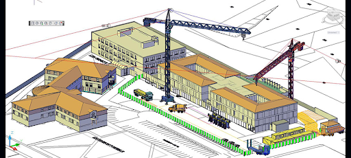
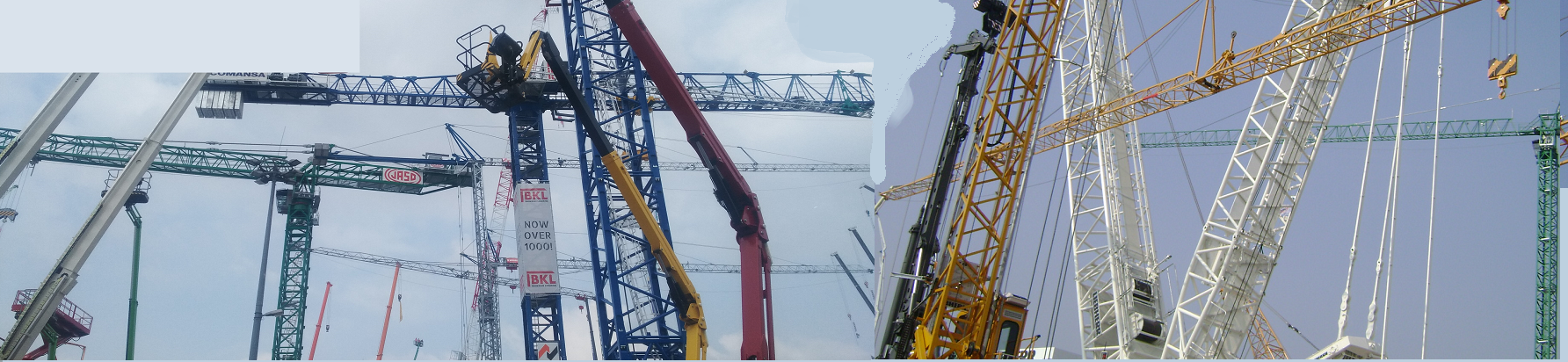
Crane layouts can be complicated especially when several cranes are present on the job site.
MéthoCAD offers tools that allow rapid, optimized and safe implementation.
Tower cranes
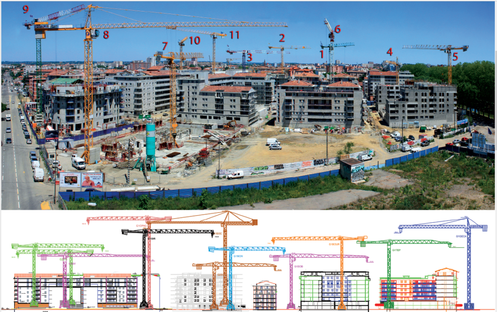
Positioning cranes on a construction site can be a challenge for the designer, particularly in situations when there are several cranes on the same site; minimum clearance must be taken into account, as well as height under hook. MethoCAD provides the solution to these problems whilst facilitating the job of the site designer.
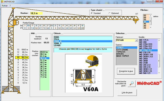
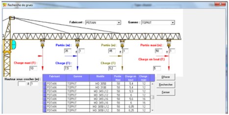
The software is shipped with an extensive database of tower cranes from the major manufacturers in the market,Potain, Liebherr, Comansa, Raimondi, Terex, Saez, Wolff which can be consulted under Windows in a dialog box. The base includes both old and new cranes as well.
The user selects the manufacturer, the range and then the model, the software displays the available frames with the corresponding hook heights as well as the boom lengths. The display of the loads according to the position of the hook is automatic.
Each crane has different bases configuration, and jibs from 35 m to 80 m with indication of single and double trolley.
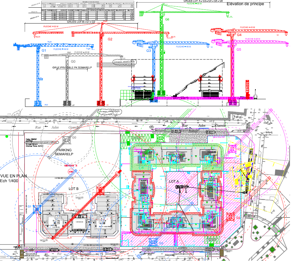
To find the right crane for the site, the user has various tools:
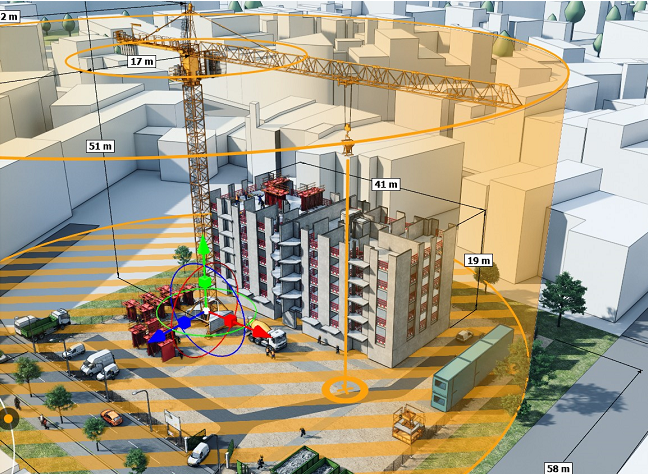
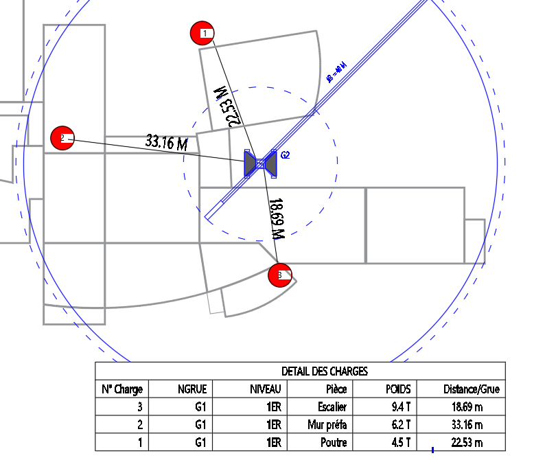
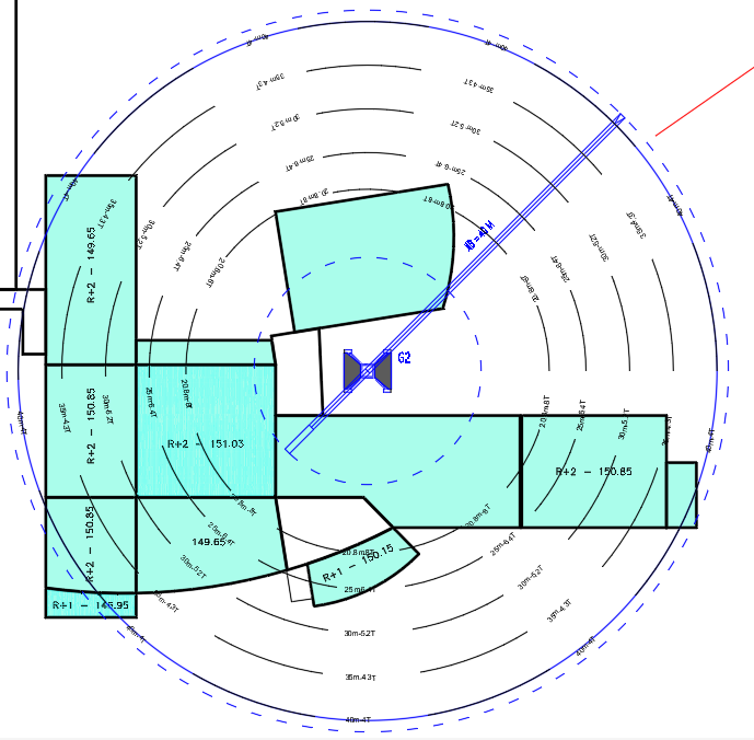
– Position the most penalizing loads on the drawing then the software displays the distances and the load table
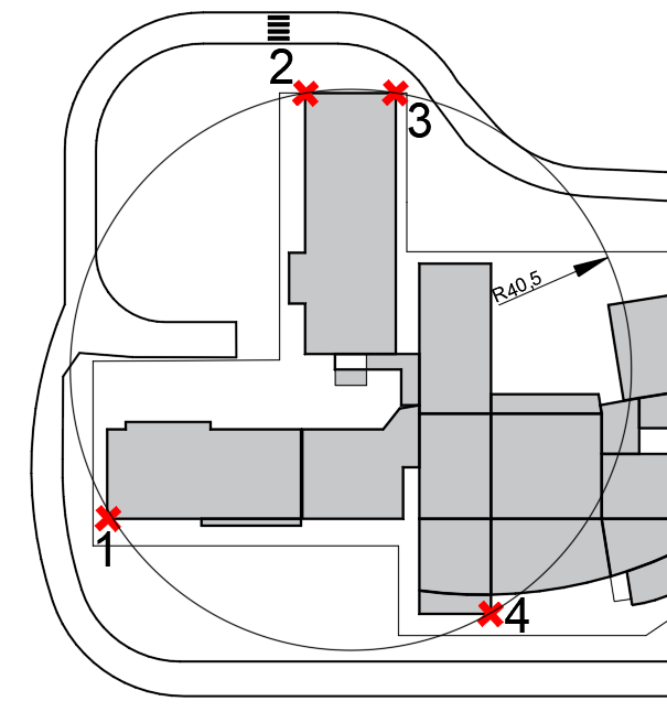
– Show the most distant points that the crane must serve then the software calculates the required jib length
– Use the dynamic blocks of cranes represented by shaded circles in top view that are stretched
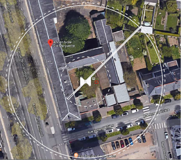
– Position the crane on the Google image of the site.
It is possible to query the database for the selection of a crane by specifying the criteria, manufacturer, type, maximum loads and at the end of the jib. It is often important to also specify the intermediate loads which can influence the choice of crane.
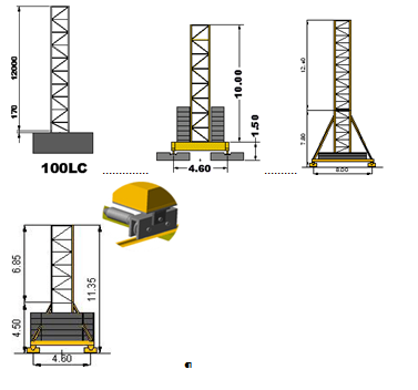
The software is supplied with a library of several hundred AutoCAD blocks making up the crane: bases, masts and jibs. Once the user has selected the parameters of his crane, these are exported under AutoCAD, the crane blocks are assembled automatically for the creation of plan and elevation views without any user intervention, errors that could be done manually are impossible. The user will not have to fetch data from manufacturers’ catalogs or AutoCAD blocks on their PC.
The load curves are inserted with the indication of the position of the hook and the maximum load. The site will thus have a working document that the manager can use to check the load to be lifted by the crane at any point on the site. The loads can also be inserted in a table.
Dimensioning of the crane is fully automatic, which eliminates the need to snap on to the precise points of the hook, the tower head or the counterjib.
Any modification such as boom length or hook height is immediate and reflected in all views.
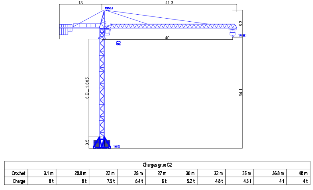
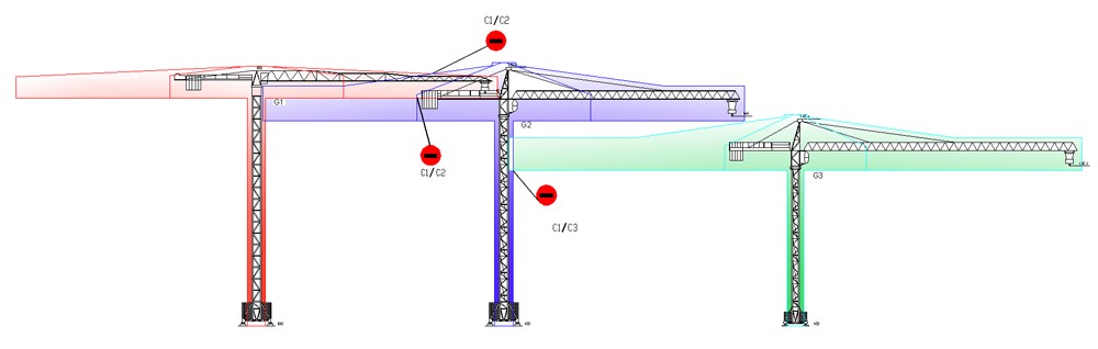
Once the plan view is drawn, the software creates the front view either in parallel orthogonal view or along the axes of the cranes.
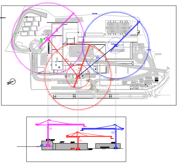
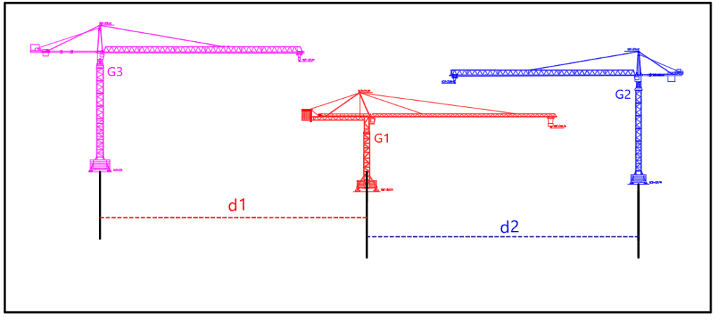
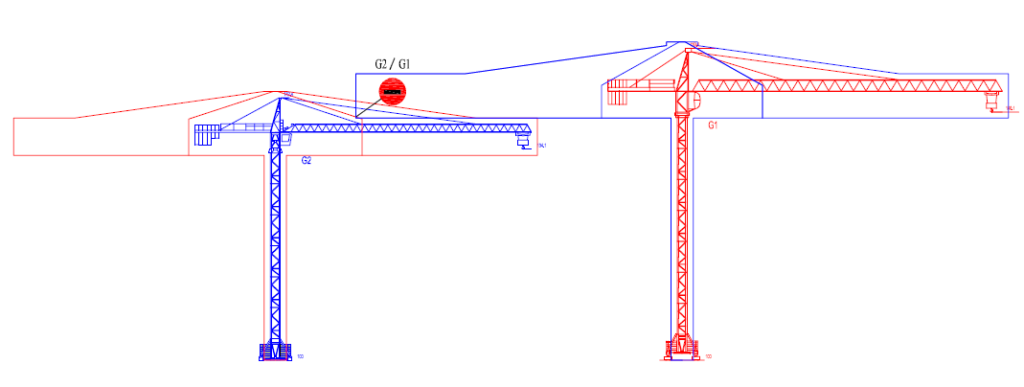
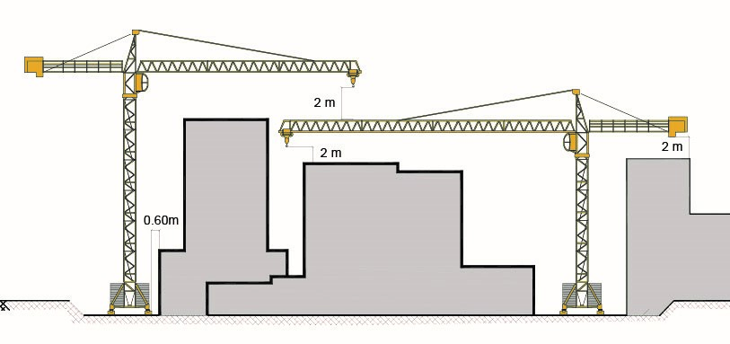
When the cranes are free standing, it is possible to check whether the minimum clearance between the cranes are respected. The software draws an envelope curve all around each crane offseted by 1m from the crane. If the envelope curves are tangent, it means that the 2m required by the regulations are respected and if the 2 curves intersect, the safety distance of 2m is not respected then the cranes must then be moved or raised.
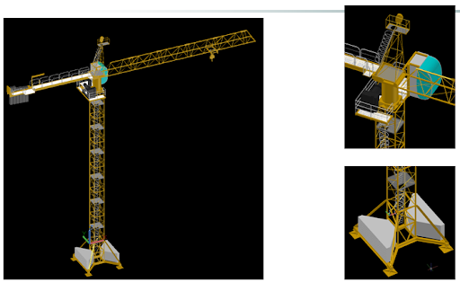
The software comes with a 3D library of realistically reproduced crane elements.
3D cranes are made in a parameterized way, the user enters data of his crane which is automatically generated in 3D.