page-header

Phasing of sails and floors

THE SAILS

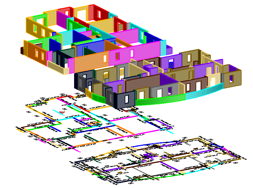
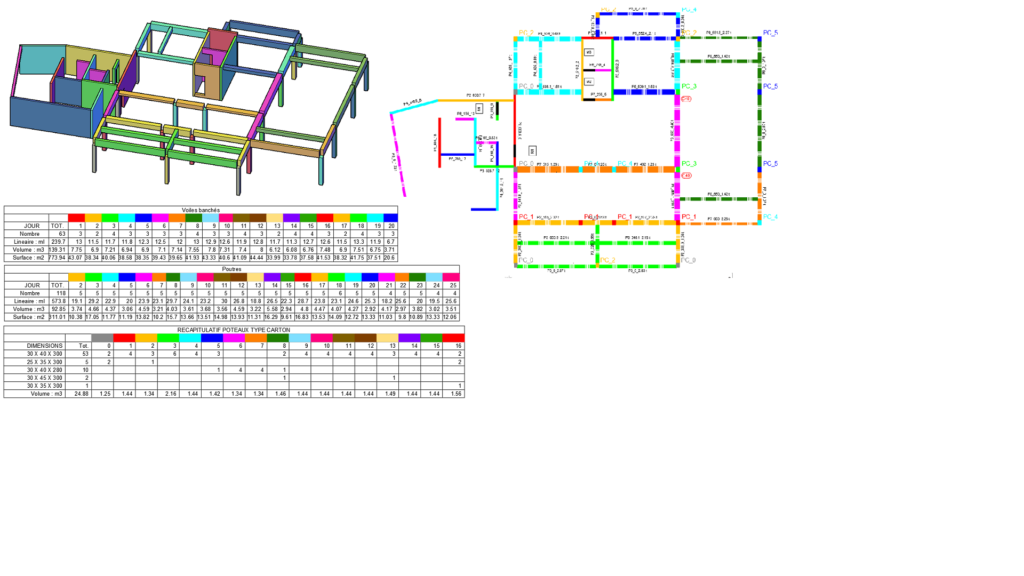
In collaboration with the site manager, the user defines the wall casting cycle from the AutoCAD background plan provided by the design office.
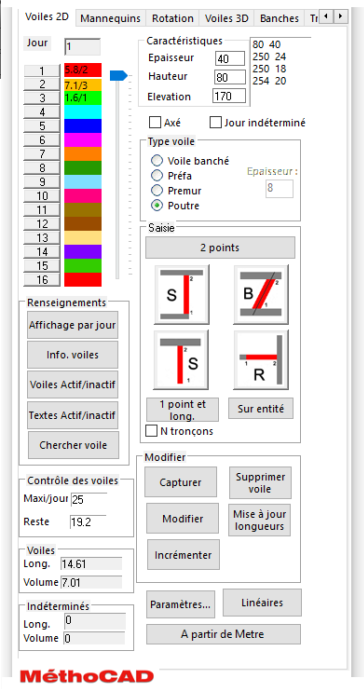
The sails are inserted using a dialog box where the user enters the characteristics of the veil, thickness, height, bottom edge and the casting day.
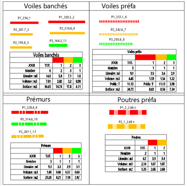
A user-customizable color is assigned to each day. It is possible to insert 3 types of sails: paneled, prefabricated and pre-walled, which are differentiated using types of lines.
The cumulative lengths cast per day and the number of sails are displayed in real time in the dialog box allowing the user to control the entry and ensure a constant average linear throughout the cycle and ‘an equivalent number of sails every day.
The sails can be modified at any time of entry, casting day, thickness, height, length. Linear and volumes are updated automatically.
It is possible to display the cycle day by day to check its consistency. The height / thickness pairs of values ​​are displayed in the box, avoiding having to re-enter them for each wall.
In case of late casting on the site, the sails can be modified by a simple click by giving the number of days of delay and the day of departure. 3D generation is automatic, which can be useful for sails of varying heights.

Phasage des voiles et planchers

THE MODELS

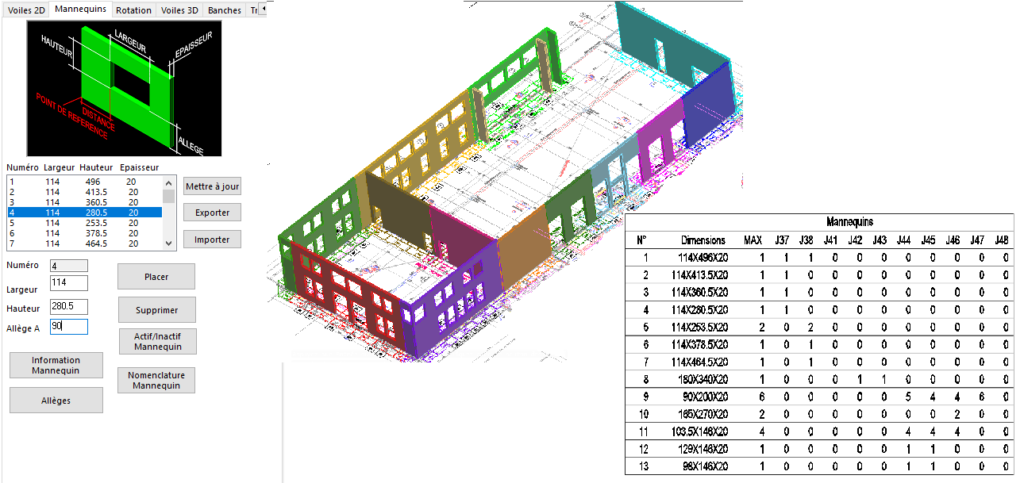
Each mannequin is defined by its width and height. The value of the lighter is specified at the time of insertion. Once inserted into the wall, it automatically takes the value of the day when the wall was poured and in the nomenclatures, the volume of concrete is deducted from the volume of the wall.

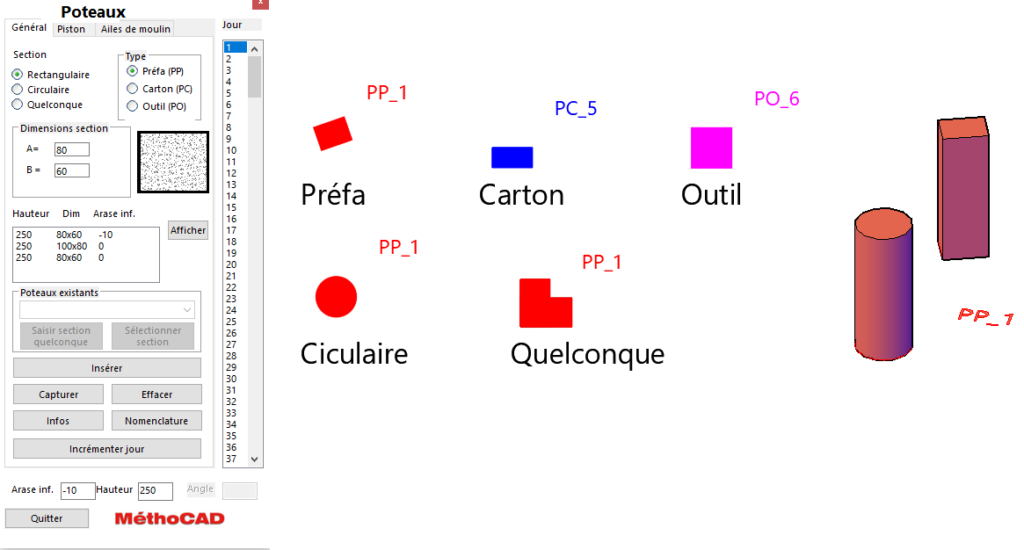
THE POLES

Columns formwork with formwork are entered as walls, whereas prefab posts are entered, or cast in place are inserted using a dialog box. The user specifies the section which can be rectangular, circular or any other, the height, the level and the day of pouring or installation.

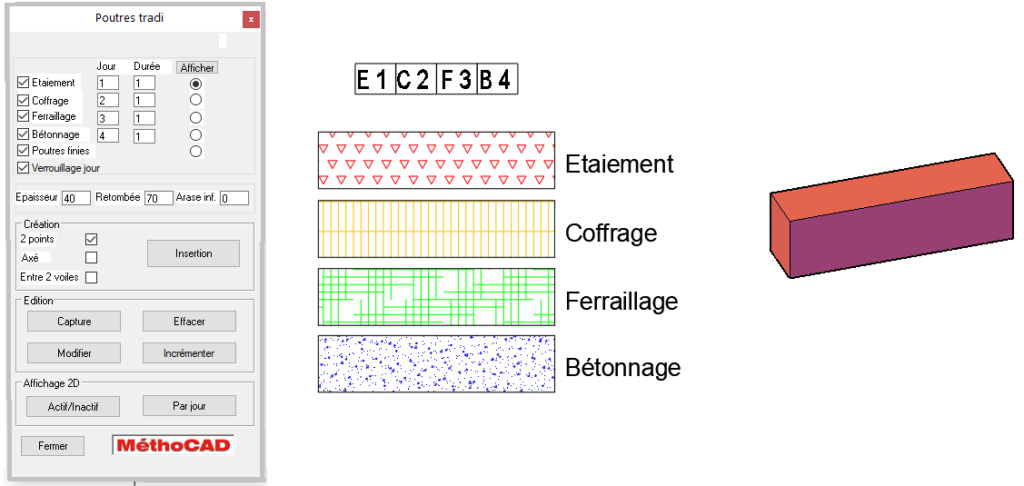
BEAMS CAST IN PLACE

Unlike prefab beams which are inserted with the wall dialog box, tradi beams are inserted using a dialog box, the user enters the dimensional characteristics and the phases, shoring, formwork, reinforcement and concreting.

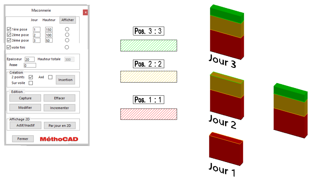
THE MASONRY

The masonry sails are entered with the box below, it is possible to assemble each veil in 3 phases which appear with hatching of different colors. In 3D, each casting phase is thus clearly visualized.

THE FLOORS

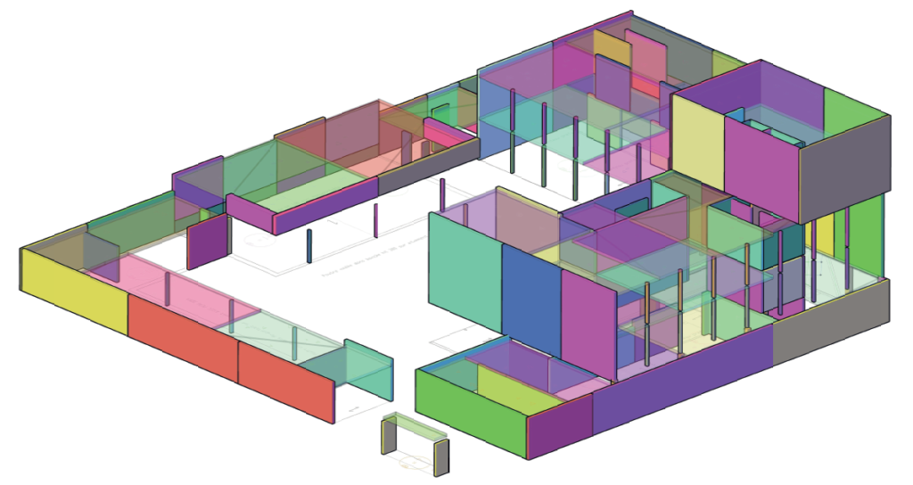
The advantage of this module is that it can automatically hatch the floor areas starting from the days when the walls were cast underneath.
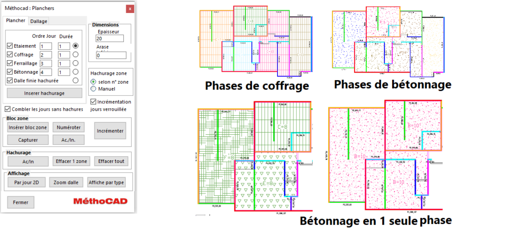
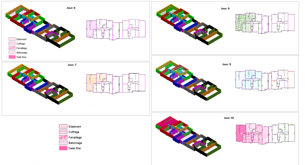
In the example below, the floor is divided into 9 zones, each zone is made over 4 days. Each phase is assigned a different layer and a different color depending on the day.
This represents 45 layers to display and color according to the phase. This manual operation can cause errors, particularly if there is a delay on the job site and all the layers of the hatch layers need to be shifted.
Other advantages are being able to automatically display the walls and floors per day to check for any inconsistencies and the 3D generation from 2D with a single click.
On the background plan, the floor zones are defined by polylines and for each zone the user can assign up to 4 different phases of shoring, formwork, reinforcement and concreting materialized by different hatch patterns.
Each phase can last 1 or more days. Each area can be made separately for the shoring, formwork and reinforcement phases, but pouring is done simultaneously on all areas at the same time.
Likewise, if a delay occurs on the site, by specifying the number of days of delay, the hatch layers are updated.

You cannot copy content of this page