Building Information Modeling
The BIM allows a precise and updated vision of all the constraints of the building site in its environment and thus a reactivity in real time to the modifications of the various participants.
THE DIGITAL MODEL
It can be obtained in different ways, from Revit software, AutoCAD software or from an IFC file.
For true collaborative work, it is best to create it in Revit. For your subcontractors in AutoCAD, you will need to export your model. The resulting model will be made up of real AutoCAD solids.
If you are provided with IFC files, you can import them directly into Revit. If you do not have Revit, the .IFC files can be imported into AutoCAD using the IFC-AutoCAD converter.
SITE LAYOUT UNDER REVIT
MéthoCAD offers construction companies the possibility to create from the digital model of the building, the installation of the site in 3D under Revit. The BIM allows to optimize the design and the construction of the site by improving the exchange of information between the actors and by supporting a global and continuous vision of the safety on the site at all the stages of the construction. The company uses it as an effective collaborative management tool throughout the operation. It provides an updated and highly documented 3D visualization of the site’s progress for increasingly complex structures. The cranes are updated in real time, positions, hook height and boom length with each change made by the designers, BIM managers or other stakeholders.
TOWER CRANES UNDER REVIT
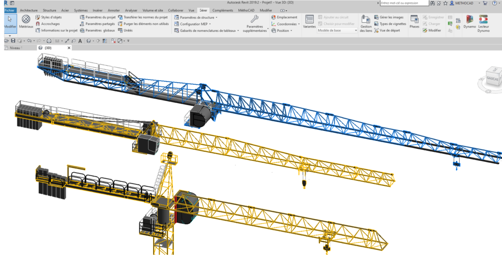
The different families of the crane’s elements representing the jib, counter-jib, mast and the base were generated in an accurate way under Revit software by respecting the morphology of the manufacturer.
The goal was to get a faithful representation of the crane in 3D as realistic as possible.
MethoCAD includes an extensive database of tower cranes data from the major manufacturers (LIEBHERR, POTAIN, RAIMONDI, COMANSA, TEREX, SAEZ…). The user selects the standard of his country, the manufacturer, the range (with tower head or topless) and the model.
For each crane model, there are several configurations of bases, for each one, the software displays the maximum hoisting height allowed.
For each jib length, the loads are displayed. For some manufacturers, the database indicates the authorized jib length for a given base type and a hoisting height.
Once the user selects the crane parameters, MethoCAD assembles the different families to generate instantly under Revit the 3D model of the crane.
The jib can be rotated, the trolley moved and the hook lowered to the lifting point to check accessibility.
Alphanumeric information like crane number, height, jib length are accessible through the Revit Properties box.
Dimension lines can also be inserted in front views.


